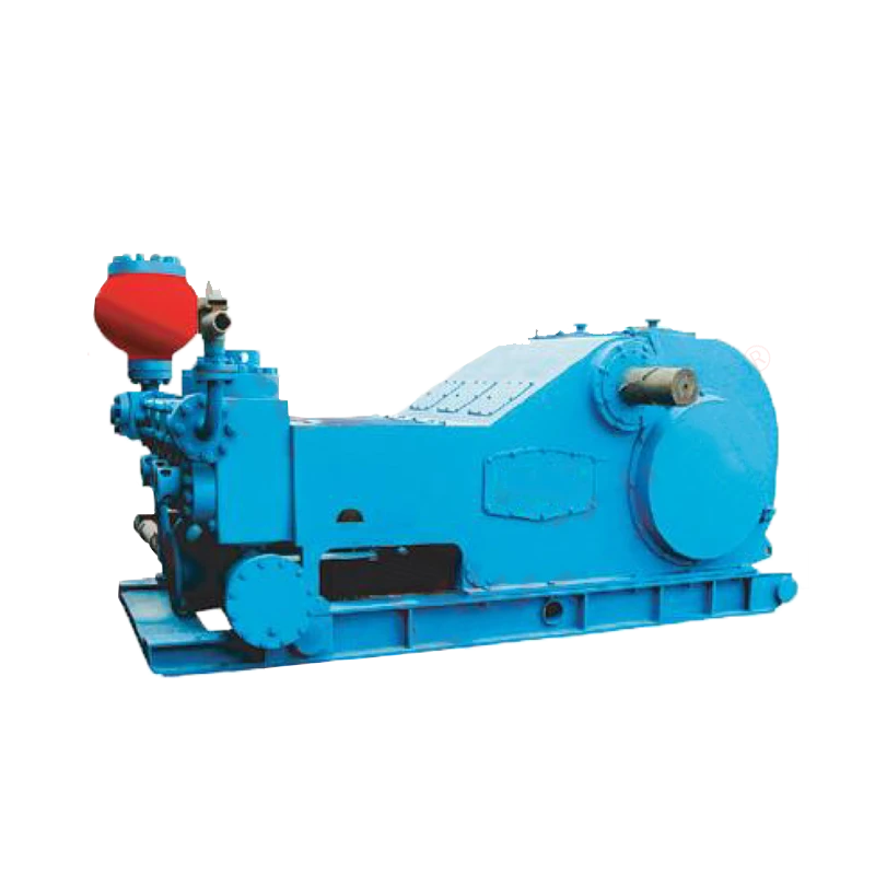
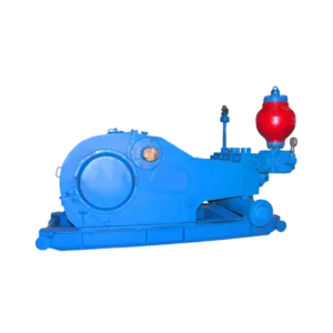
3NB1300 Mud Pump
Frame It is in structure of steel plate welding, the bearing block of transmission shaft and upper and bottom bases of crank shaft are cast steel, the bearing block of crank adopts the structure of width plate and stiffened plate reinforcement, and the rigidity is good and strength is high.
Parameter of 3NB1300 Mud Pump
STRUCTURAL FEATURES OF RS-3NB1600/1300
Frame It is in structure of steel plate welding, the bearing block of transmission shaft and upper and bottom bases of crank shaft are cast steel, the bearing block of crank adopts the structure of width plate and stiffened plate reinforcement, and the rigidity is good and strength is high.
Crank shaft Casted by alloy steel.
Wheel set of transmission gear It is in involute herringbone gear, adopts medium hard tooth flank, and the drive torque is high and the operation is smooth.
Pinion It is the forged by alloy steel, and either of two ends of transmission shaft can be installed with pulley.
Crosshead It adopts ductile iron cast and has the good antifriction performance. The guide plate adopts the structure of upper and lower guide plates, which can adjust concentricity through adding washer at the lower guide plate.
Hydraulic cylinder It is the forged by alloy steel. It is in the form of straight-way type cylinder. The size of cylinder is small, the volumetric efficiency is high, and the taper of valve seat hole is 1:6 and has steps. It is suitable for operation under high pressure. The gland and flange on cylinder adopt the connection of saw tooth thread, and flange is fastened on cylinder by bolts, which is convenient for speeding disassembly during service. The surface of cylinder is treated by chemical nickel and phosphorus plating to enhance the performance of anti-corrosion.
Valve assembly NB1300 and NB1600 mud pumps adopt API 7# valve. The parts of hydraulic cylinder, cylinder,
plunger, valve, valve seat, valve spring, sealing part, valve cap and cylinder cap, etc. at the fluid end can be interchanged.
Lubrication system Oil wiper and oil channel are installed at the position of pinion. The lube is delivered through oil channel to the two bearings of transmission shaft and crank shaft and lubricating point on the top of guide plate.
The forced lubrication device can be matched on the outside of machine frame.
| Cylinder Diameter | mm | φ180 | φ170 | φ160 | φ150 | φ140 | φ130 | |||
| Discharge pressure | Mpa | 18.4 | 20.7 | 23.4 | 26.6 | 30.5 | 34.5 | |||
| Stroke | Input power | Output power | Discharge capacity (L/s) | |||||||
| Min-1 | KW | Horse power | KW | Horse power | ||||||
| 120 | 956 | 1300 | 860 | 1170 | 46.6 | 41.5 | 36.8 | 32.3 | 28.2 | 24.3 |
| 110 | 876 | 1191 | 789 | 1073 | 42.7 | 38.0 | 33.7 | 29.6 | 25.9 | 22.3 |
| 100 | 797 | 1083 | 717 | 975 | 38.8 | 34.5 | 30.6 | 26.9 | 23.5 | 2025 |
| 90 | 717 | 975 | 645 | 878 | 35.0 | 31.1 | 27.6 | 24.2 | 21.2 | 18.2 |
| 50 | 398.4 | 542 | 359 | 487.5 | 19.4 | 17.25 | 15.3 | 13.45 | 11.75 | 10.1 |
| 1 | 7.96 | 10.80 | 7.171 | 9.75 | 0.466 | 0.345 | 0.306 | 0.269 | 0.235 | 0.2025 |
( Mechanical efficiency 90%, coefficient of fullness α=100%, and volumetric efficiency 100% )
Want to Know More Detail About This Drilling Equipment?
相关产品
-
Mud Pump
A45T8A DUPLEX POWER PUMPS
-
Mud Pump
PAH Series PAH350 Mud Pump
-
Mud Pump
W Series W446 Mud Pump
-
Mud Pump
F Series F1000 Mud Pump
